 It’s well known that temperature affects pendulum clocks. On a warm day the pendulum rod will expand and the clock will run a little slower. Various methods are used to compensate for this effect, with varying degrees of success. The most accurate pendulum clocks were always kept in a controlled temperature environment. But this is not always practical.
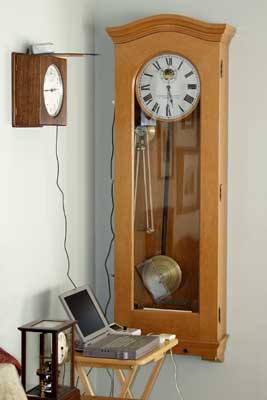
I have wondered if a good clock case might protect the pendulum inside from daily fluctuations of temperature. Or will the temperature inside a clock follow the changing room temperature? To answer this question, I studied a commercial clock that’s relatively common and in a relatively good case. The Standard Electric master clock, shown here, is in a sturdy oak case with a door that fits tightly but has no gasket to really seal it.
To make the necessary measurements I modified a MicroSet 3 to have two temperature sensors, and created a special “technical mode” that would output two alternating temperature readings to the computer. I used the Windows interface software to capture the readings and graph them. I placed one temperature sensor inside the clock case by removing the top latch and passing the cable through the existing hole. The sensor was arranged near the center of the case, just below the dial. The second sensor was suspended in the open air at about the same height. You can see it projecting from the gallery clock in the picture. Readings were captured on a laptop computer.
The resulting graph shows quite clearly that, even with this modest clock case, the temperature inside stays cooler than the room temperature outside. In the graph below, the red columns are the temperature inside the clock. The green line is the temperature in the room. The graph begins with the end of the previous evening. The clock interior and the room outside were at nearly the same temperature.
In the morning the furnace came on and produced a little spike in the room temperature (the green line). The clock case began to rise shortly thereafter. The two stabilized at 68 degrees for about two hours, and then the room began to get warmer. It was May 10th in Santa Barbara, and it was going to be a warm day.
The room got hotter and the clock case followed, but not at the same pace. The hollow case maintained a separate, insulated space for the pendulum. Around 5 PM the room temperature began to decline a little, as shown in the graph. A door to the outside, in the same room that the clock was in, had been open all day. Shortly after 5 PM I closed that door. The room, which had begun to cool, continued to climb in temperature because it has western exposure and the sun was bright. Direct sunlight did not fall on the clock.
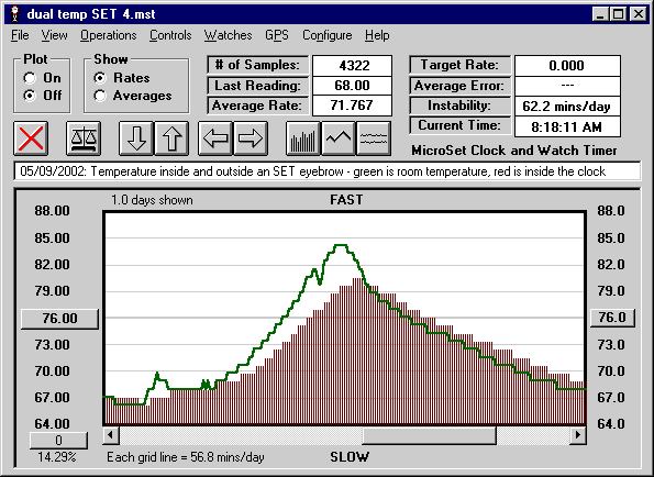
The room reached a maximum temperature around 6 PM. At this time the room was 84 degrees and the clock interior was 79. As the room cooled, the clock case tended to preserve the accumulated heat. The temperature inside lagged the temperature outside.
I computed an average temperature for the room and the inside of the clock over the 24 hours shown. They’re quite close. The average temperature for the room was 72.581 degrees and 72.158 for the clock interior. For precision pendulums, this may be a significant difference, but it’s a small difference. Perhaps more significant is the fact that the pendulum was protected from the high by five degrees. The more change a pendulum is subjected to, the more physical stress it will be subjected to, and it may be more likely to suffer an unsymmetrical change in expansion/contraction. In homes with air conditioning these temperature changes would be very modest and the case would probably just eliminate the small heating and cooling cycle.
Additional experiments revealed substantial stratification in the room air outside the clock. In the afternoon, the temperature at the top of the clock was five degrees warmer than the air at the bottom of the clock. I have not yet measured stratification inside the clock case, but this is likely to exist as well. This is not good news for temperature compensation, because it means the bob will tend to be cooler than the rod. Temperature compensation usually relies on upward expansion of the bob to counter downward expansion of the rod. If the bob is cooler, it will tend to reduce the compensation it provides.
I can think of at least three causes for the clock interior temperature to climb on a warm day:
1) Warm air is exchanged around the door opening.
2) Heat passes through the glass door and, to a lesser extent, the wood sides.
3) Visible light heats the interior surfaces of the clock and warms it by greenhouse effect.
Additional experiments can determine which of these effects are more significant. Air exchange could be minimized by seals or gaskets. Transmission through the case could be minimized by a double paned glass or hollow sides. Radiation could be minimized by choice of location or using less glass. These are not new ideas. They were described by Ward Goodrich in 1905. See The Modern Clock, Chapter XXIII, page 451.
Should anyone wish to conduct their own experiments with temperature, a special MicroSet can be ordered with two temperature sensors.
Seven day results
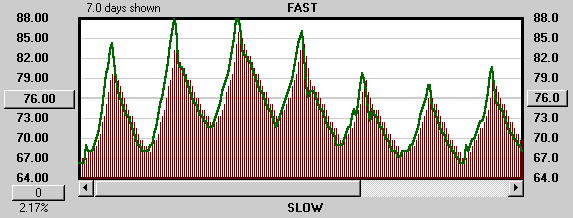
The graph below shows the performance of the system after seven days. The clock temperature tracks the outside temperature pretty closely. There are bigger discrepancies on hot days, but on cooler days, the average is about the same. For this seven day period, the average temperature was 73.855 degrees outside the clock, and 73.753 degrees inside the clock.
My conclusion is that, over time, this clock case does not significantly change the average temperature of the clock. But it does protect the clock somewhat from the extremes, which is a benefit.
 The Therminator
This leads me to an idea that developed during the course of this experiment. If the clock case doesn’t protect the clock from ambient changes, how about controlling the temperature inside the case?
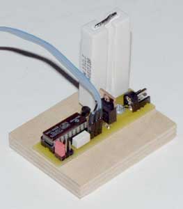
I imagined the “Therminator” — a thermostatically controlled heater to go inside a clock and banish temperature variations by keeping the inside of the clock artificially heated. I designed and built a simple prototype, shown here. It uses a PIC chip to switch power to a pair of power resistors used to generate heat. A digital temperature sensor is placed at the end of a ribbon cable and located near the center of the clock case. A jumper block allows you to set the temperature trip point at 80, 90, or 100 degrees. Power is provided by a 24 volt, 1 amp AC adaptor which develops 22 watts of heat in the two resistors.
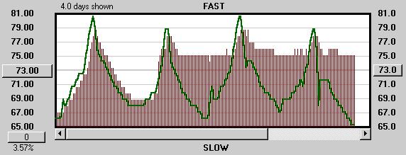
Preliminary results are very encouraging. Shown below are the last four days of measurements inside the clock case. The first day the clock was unaltered and the temperatures followed a normal 24 hour cycle. On the second day the Therminator was installed. Immediately the clock began to heat up. As the heat of the day surpassed the temperature of the clock case, it drew up the interior temperature. But at night, as the room cooled down, the Therminator maintained the temperature inside the clock case to an accuracy of one degree.
The current configuration of the Therminator did not have enough power to raise the internal temperature sufficiently to keep it warmer that the maximum daytime temperature. But it easily kept it from cooling off at night, and it’s reasonable to believe that a Therminator with more power will be able to keep the clock warmer; or that a clock case designed with better insulation would work with these settings..
In 24 hours the room temperature changed by 15 degrees. With the insulation of the clock case, the clock temperature changed by just 12 degrees. With the Therminator installed, the clock temperature changes by just 3 degrees. That’s a significant improvement.
Bryan Mumford
Santa Barbara, California
May 21, 2002
